Control Joints (part 1)
Control joints are small gaps formed in floors and walls to allow localised movements that arise from drying shrinkage, thermal gain/loss and creep.
Control joints in walls
For wall applications these gaps are normally filled with a sealant which is laid on a closed cell polyethylene backer rod. Care must be taken to select the correct sealant and control must be exercised during site installation to ensure that the manufacturer’s recommended width to depth ratio is maintained. Sealant should be regarded as a maintenance item and the sealant replaced as it ages over time.
Control joints in floors
Sealants can present problems when used as control joints in floors and increasingly preformed jointing systems are employed as they are more resistant to damage, protect the edges of expensive paving and, as they are manufactured in a factory environment and not formed on site, they offer consistent performance.
Most international standards advise that preformed control joints should have metal edge profiles if they are to be used in high traffic areas and this is reflected in both of the current British Standards relating to floor tiling:
- BS 5385 Part 3: 2007 ‘ Code of Practice for the design and installation of internal and external ceramic and mosaic floor tiling in normal conditions’
- BS 5385 Part 5: 2009 ‘Code of Practice for the design and installation of terrazzo, natural stone and agglomerated stone tile and slab flooring’
Where should control joints be located?
Bays, Bay Sizes and International Norm
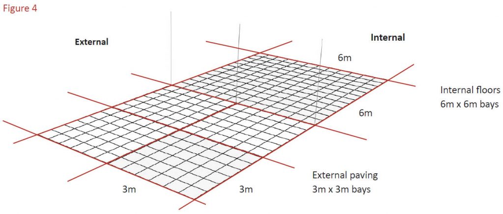
Control joints are inserted between paving to form bays so that deflections arising from drying shrinkage, thermal gain and loss and creep can be divided up. Each bay is isolated from adjoining bays and control joints open and close in response to the loads transferred. Figure 4 above shows a typical bay configuration.
The size of bays recommended in International Standards vary but increasingly it is becoming the norm for:
- Control joints in internal paving to be installed forming 6 metre x 6 metre bays.
- Control joints in external paving to be installed forming 3 metre x 3 metre bays.
Control joints in external bays in hot climates should also employ a wider control joint than that used internally to allow for the greater movement generated by temperature change.
How are the values for recommended bay sizes derived?
The component forces underlying the recommendation of bay size derive directly from the magnitude of drying shrinkage and thermal expansion and contraction of materials employed.
Drying shrinkage
The typical drying shrinkage of a screed or semi-dry mortar bed screed is approximately 0.2% of the length of the span. Typically C20/25 concrete will exhibit a drying shrinkage of 0.3% of the span however the reduced water content (and cube strength) of screeds and semi-dry bedding means that this shrinkage factor is reduced. The shrinkage of a 6 metre span of semi-dry mortar bedding is broken down into two elements:
- Bay foreshortening where the length of the bay side is reduced. This is normally represented as 0.15% of bay length which is equivalent to 0.9mm across a 6 metre span.
- Micro-fissuring where micro-cracking within the semi-dry mortar bay represents the other 0.05% shrinkage factor. Provided control joints are installed at bay perimeters this micro-cracking has no effect upon either finishes or bay length.
Hence a drying shrinkage factor of approximately -1.0mm at the perimeter of 6 metre bays may be considered to meet current International Codes of Practice.
Thermal expansion and contraction
The current British Standard Code of Practice BS 5385: Part 5 2009 advises that: ‘Where high temperatures are expected … an assessment of the likely temperature range and corresponding linear changes in the flooring should be made to determine whether and where any additional allowance for movement is necessary.’
The thermal expansion and contraction of the flooring will depend upon the:
a) Linear thermal coefficient of expansion of the flooring materials
b) Temperature differentials experienced by the finishes
c) Maximum span between control joints.
Example
Taking as an example the linear thermal coefficient of expansion of granite as approximately 8 x 10⁻⁶mm/mm/°K and applying it to a thermal variation of +/-20°C and a 6.0 metre span results in a movement cycle equal to: 8.0 x 10-6 x 6000 x 20 = +/-.96mm
Hence, a control joint installed forming 6.0 metre bays may have to accommodate +/-1.0mm of movement due to thermal cycling.


